Monday, July 18, 2011

Tutorial Class 6: UPPER LAYER OF THE OSI MODEL

In our last class, we had a brief introduction to the OSI model—the seven-layer model used to help application developers design applications that can run on any type of system or network. Each layer has its special jobs and select responsibilities within the model to ensure that solid, effective communications do occur.

In this tutorial class, you’ll get to know the functions defined at each layer of the upper layer of the OSI model.

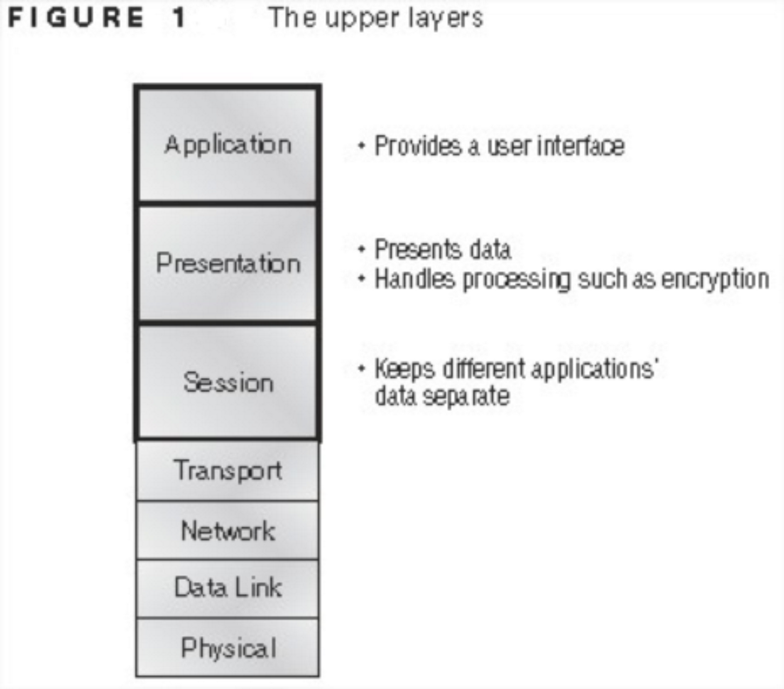
The Application Layer

The Application layer of the OSI model is the layer where users actually communicate to the computer. This layer only comes into play when access to the network is going to be needed soon. It’s just like browsing the internet with Internet Explorer or Mozilla Firefox. The browser will respond to requests such as using HTTP by attempting to access the Application layer.

The Application layer acts as an interface between the actual application program and the next layer (presentation layer) by providing ways for the application to send information down through the protocol stack. This means that the browser doesn’t truly reside within the Application layer—it interfaces with Application layer protocols when it needs to deal with resources on the network.
The Application layer is also responsible for identifying and establishing the availability of the intended communication partner and determining whether sufficient resources for the intended communication exist.

The Application layer acts as an interface between the actual application programs. Simply put, applications like Microsoft Word do not reside at the Application layer but instead interfaces with the Application layer protocols, such as FTP and TFTP.

The Presentation Layer
The Presentation layer gets its name from its purpose: It presents data to the Application layer and is responsible for data translation and code formatting.
The Presentation layer ensures that data transferred from the Application layer of one system can be read by the Application layer of another one. The data received from the application layer is translated into a language (code) that the presentation layer understands. Computers receive this generically formatted data and then convert the data back into its native format for actual reading (for example, EBCDIC to ASCII). Data compression, decompression, encryption, and decryption are associated with this layer.

The Session Layer
The Session layer basically keeps different applications’ data separate from other applications’ data. It sets up, manages, and then tears down sessions between Presentation layer entities. This layer also provides dialog control between devices, or nodes.

So, now you know the three upper layers of the OSI model; the application, presentation and session layer and the respective roles they play in information and communication transfer.
In summary, the following services are available at the layers:
•    Application layer: File, print, message, database and application services.
•    Presentation layer: Data encryption, compression and translation services.
•    Session layer: Dialog control.

In our next tutorial class, you’ll get to know the functions defined at each layer of the lower layer of the OSI model.


Monday, July 11, 2011

Tutorial Class 5: The OSI Reference Model

In our last class, we got to understand the basics of an internetwork through examples. In this tutorial class, I’ll be introducing you to internetworking models. This simply talks about the Open Systems Interconnection (OSI) reference model which was created by the International Organization for Standardization (ISO) to break the barrier of computers typically communicating only with computers from the same manufacturer.
The OSI model is the primary architectural model for networks. It describes how
data and network information are communicated from an application on one computer through the network media to an application on another computer by breaking it into layers.

What is a reference model?
A reference model is a conceptual blueprint of how communications should take place. It addresses all the processes required for effective communication and divides these processes into logical groupings called layers. When a communication system is designed in this manner, it’s known as layered architecture.
To understand it better, let’s take the following scenario:

You and some friends want to start a company. One of the first things you’ll do is sit down and think through what tasks must be done, who will do them, the order in which they will be done, and their relationship with each other. These tasks will be grouped into departments. Each of your departments has its own unique tasks, keeping its staff members busy and requiring them to focus on only their own duties.
These departments are simply the layers of the communication system. For things to run smoothly, the staff of each department will have to trust and rely heavily upon the others to do their jobs and competently handle their unique responsibilities. In your planning sessions, you would probably take notes, recording the entire process to facilitate later discussions about standards of operation that will serve as your business blueprint, or reference model.

Similarly, software developers can use a reference model to understand computer communication processes and see what types of functions need to be accomplished on any one layer. If they are developing a protocol for a certain layer, all they need to concern themselves with is that specific layer’s functions, not those of any other layer. Another layer and protocol will handle the other functions. The technical term for this idea is  binding . The communication processes that are related to each other are bound, or grouped together, at a particular layer.

Advantages of Reference Models
The OSI model is hierarchical, and the same benefits and advantages can apply to any layered model. The primary purpose of all such models, especially the OSI model, is to allow different vendors’ networks to interoperate.

Advantages of using the OSI layered model include, but are not limited to, the following:
•    It divides the network communication process into smaller and simpler components, thus aiding component development, design, and troubleshooting.
•    It allows multiple-vendor development through standardization of network components.
•    It encourages industry standardization by defining what functions occur at each layer of the model.
•    It allows various types of network hardware and software to communicate.
•    It prevents changes in one layer from affecting other layers, so it does not hamper development.

The OSI Reference Model
One of the greatest functions of the OSI specifications is to assist in data transfer between hosts from different vendors—meaning, for example, that they enable us to transfer data between a Unix host and a PC or a Mac.
The OSI isn’t a physical model, though. Rather, it’s a set of guidelines that application developers can use to create and implement applications that run on a network. It also provides a framework for creating and implementing networking standards, devices, and internetworking schemes.

The OSI has seven different layers, divided into two groups. The top three layers define how the applications within the end stations will communicate with each other and with users. The bottom four layers define how data is transmitted end to end. Figure 1 shows the three upper layers and their functions, and Figure 2 shows the four lower layers and their functions.
The user interfaces with the computer at the Application layer and also the upper layers are responsible for applications communicating between hosts.
The four bottom layers are responsible for networking or network addresses. They define how data is transferred through a physical wire or through switches and routers. These bottom layers also determine how to rebuild a data stream from a transmitting host to a destination host’s application.

The following network devices operate at all seven layers of the OSI model:
•    Network management stations (NMSs)
•    Web and application servers
•    Gateways (not default gateways)
•    Network hosts

The OSI reference model has seven layers:
•    Application layer (layer 7)
•    Presentation layer (layer 6)
•    Session layer (layer 5)
•    Transport layer (layer 4)
•    Network layer (layer 3)
•    Data Link layer (layer 2)
•    Physical layer (layer 1)

So, I guess with this short class, you’ve gotten a brief introduction to the OSI model—the seven-layer model used to help application developers design applications that can run on any type of system or network. Each layer has its special jobs and select responsibilities within the model to ensure that solid, effective communications do occur.

In our next tutorial class, you’ll get to know the functions defined at each layer of the upper layer of the OSI model.

.

Tuesday, July 5, 2011

Free materials!

For your free CCNA materials, click here.

Tutorial Class 4

In this class, I’ll be giving you the answers to the self tests in the previous class and shed more light on internetworking with some examples.

The answers to the previous self tests are as follows:

For the first question, in order for host A to ping (that is, communicate with ) host B, you need a crossover cable to connect the two switches together. I hope you remember from our Ethernet cabling class that to connect two hosts, you use a crossover cable.

For the second question, there are a variety of cables in use. For the connection between the switches,
we’d obviously use a crossover cable. We have a console connection between the router console and the computer that uses a rolled cable. Plus, the connection from the router to the switch is a straight-through cable, which is the same for the hosts to the switches.

I hope you understand those answers. If you don’t,  just go over the previous classes on Ethernet cabling and networking devices.

We’ll be understanding more about internetworking with the figure below.


I guess you remember this figure from our last class. Looking at the figure, how many collision domains and broadcast domains are in this internetwork?

Hopefully, you answered nine collision domains and three broadcast domains! Remember, only routers break up broadcast domains by default. And since there are three connections, that gives you three broadcast domains. But where are the nine collision domains?
The all-hub network is one collision domain; the bridge network equals three collision domains. Add in the switch network of five collision domains—one for each switch port—and you’ve got a total of nine.


The figure below which shows switched networks creating an internetwork is what is typically found today.


Okay, here LAN switches are placed at the center of the network so the routers are connecting only logical networks together. If I implemented this kind of setup, I’ve created virtual LANs (VLANs), something I’m going to tell you about in later classes. But it is really important to understand that even though you have a switched network, you still need a router to provide your inter-VLAN communication, or internetworking. Don’t forget that!
Obviously, the best network is one that’s correctly configured to meet the business requirements of the company it serves. LAN switches with routers, correctly placed in the network, are the best network design.

Now each port on the switch is a separate collision domain and each VLAN is a separate broadcast domain. But you still need a router for routing between VLANs. How many collision domains do you see here? I’m counting 10—remember that connections between the switches are considered a collision domain!


So now that you’ve gotten an introduction to internetworking and the various devices that live in an internetwork, in our next class, I will be introducing you to internetworking models. This simply talks about the  Open Systems Interconnection (OSI) reference model which was created by the International Organization for Standardization (ISO) to break the barrier of computers typically communicating only with computers from the same manufacturer.


YOUR BUSINESS AND ITS NETWORK

Hey, I know wireless networking is what’s popping now, but not everyone has the luxury of using a wireless network. So, I’ll be telling you about how to use networking cables in your business.
For the basic business network where every computer system can communicate with the others, you’ll need two basic things; a network (Ethernet cable) and a networking device (see tutorial for more info).

Suppose you have ten employees, each using a computer system, you’ll need yards of Ethernet cable and a router. Now when I say ‘yards’, I don’t mean just get really long cables without measuring your business/office space. It’ll be good to note that the longer the cable, the more money you spend. Also, the networking device you get depends on your budget. A router is more expensive than a switch, which in turn costs more than a hub. I suggested a router because of its capabilities, but if your hands are a bit tied, a few switches would equally do a great job.

If the computer systems are in different offices, you might want to place your networking device at the center of the whole network so as to reduce the length of the networking cable used and the distance between the devices and the computer systems.

YOUR BUSINESS AND ITS NETWORK