Showing posts with label Information technology. Show all posts

Monday, July 18, 2011

Tutorial Class 6: UPPER LAYER OF THE OSI MODEL

In our last class, we had a brief introduction to the OSI model—the seven-layer model used to help application developers design applications that can run on any type of system or network. Each layer has its special jobs and select responsibilities within the model to ensure that solid, effective communications do occur.

In this tutorial class, you’ll get to know the functions defined at each layer of the upper layer of the OSI model.

The Application Layer

The Application layer of the OSI model is the layer where users actually communicate to the computer. This layer only comes into play when access to the network is going to be needed soon. It’s just like browsing the internet with Internet Explorer or Mozilla Firefox. The browser will respond to requests such as using HTTP by attempting to access the Application layer.

The Application layer acts as an interface between the actual application program and the next layer (presentation layer) by providing ways for the application to send information down through the protocol stack. This means that the browser doesn’t truly reside within the Application layer—it interfaces with Application layer protocols when it needs to deal with resources on the network.
The Application layer is also responsible for identifying and establishing the availability of the intended communication partner and determining whether sufficient resources for the intended communication exist.

The Application layer acts as an interface between the actual application programs. Simply put, applications like Microsoft Word do not reside at the Application layer but instead interfaces with the Application layer protocols, such as FTP and TFTP.

The Presentation Layer
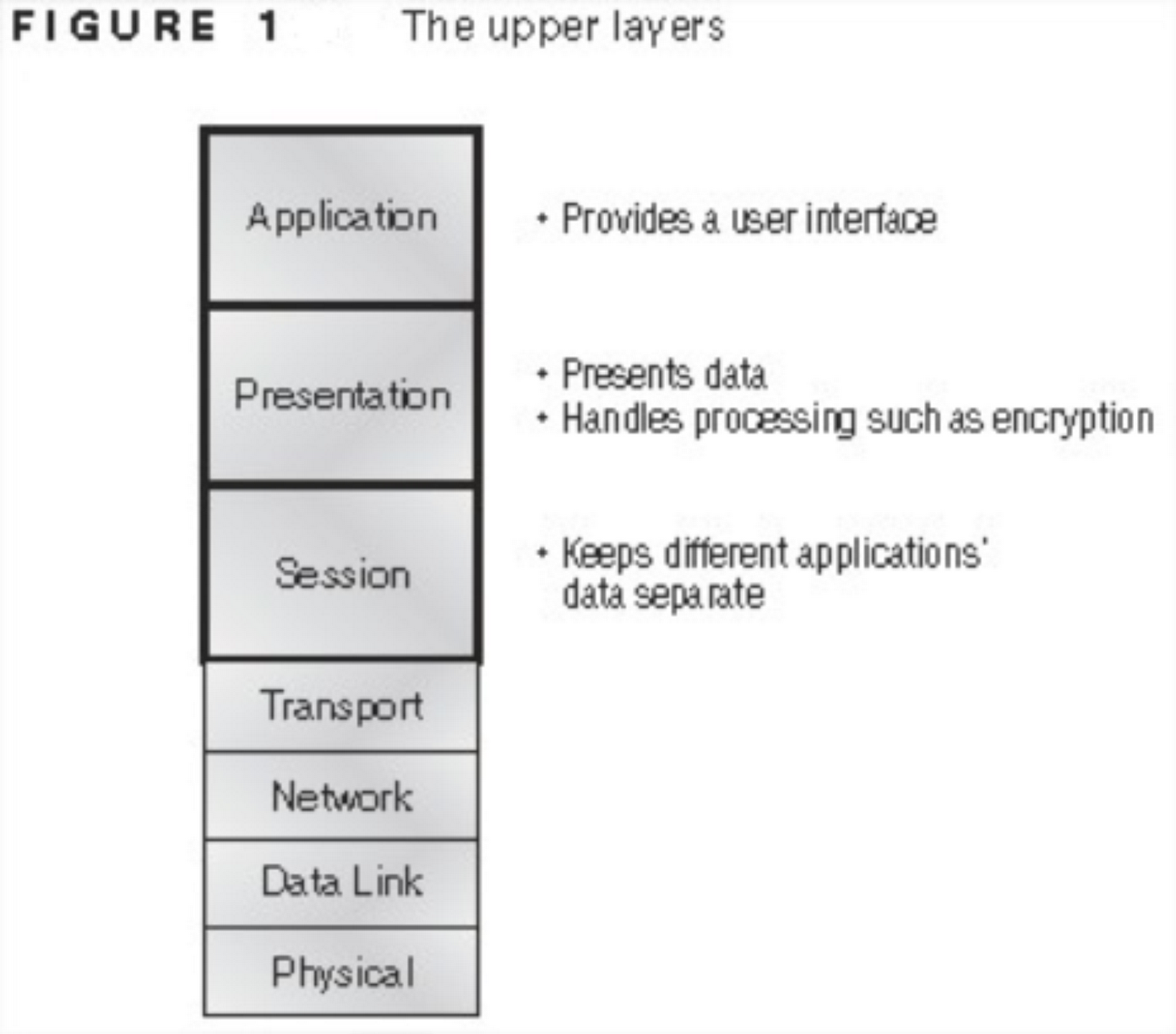
The Presentation layer gets its name from its purpose: It presents data to the Application layer and is responsible for data translation and code formatting.
The Presentation layer ensures that data transferred from the Application layer of one system can be read by the Application layer of another one. The data received from the application layer is translated into a language (code) that the presentation layer understands. Computers receive this generically formatted data and then convert the data back into its native format for actual reading (for example, EBCDIC to ASCII). Data compression, decompression, encryption, and decryption are associated with this layer.

The Session Layer
The Session layer basically keeps different applications’ data separate from other applications’ data. It sets up, manages, and then tears down sessions between Presentation layer entities. This layer also provides dialog control between devices, or nodes.

So, now you know the three upper layers of the OSI model; the application, presentation and session layer and the respective roles they play in information and communication transfer.
In summary, the following services are available at the layers:
•    Application layer: File, print, message, database and application services.
•    Presentation layer: Data encryption, compression and translation services.
•    Session layer: Dialog control.

In our next tutorial class, you’ll get to know the functions defined at each layer of the lower layer of the OSI model.


Monday, July 11, 2011

Tutorial Class 5: The OSI Reference Model

In our last class, we got to understand the basics of an internetwork through examples. In this tutorial class, I’ll be introducing you to internetworking models. This simply talks about the Open Systems Interconnection (OSI) reference model which was created by the International Organization for Standardization (ISO) to break the barrier of computers typically communicating only with computers from the same manufacturer.
The OSI model is the primary architectural model for networks. It describes how
data and network information are communicated from an application on one computer through the network media to an application on another computer by breaking it into layers.

What is a reference model?
A reference model is a conceptual blueprint of how communications should take place. It addresses all the processes required for effective communication and divides these processes into logical groupings called layers. When a communication system is designed in this manner, it’s known as layered architecture.
To understand it better, let’s take the following scenario:

You and some friends want to start a company. One of the first things you’ll do is sit down and think through what tasks must be done, who will do them, the order in which they will be done, and their relationship with each other. These tasks will be grouped into departments. Each of your departments has its own unique tasks, keeping its staff members busy and requiring them to focus on only their own duties.
These departments are simply the layers of the communication system. For things to run smoothly, the staff of each department will have to trust and rely heavily upon the others to do their jobs and competently handle their unique responsibilities. In your planning sessions, you would probably take notes, recording the entire process to facilitate later discussions about standards of operation that will serve as your business blueprint, or reference model.

Similarly, software developers can use a reference model to understand computer communication processes and see what types of functions need to be accomplished on any one layer. If they are developing a protocol for a certain layer, all they need to concern themselves with is that specific layer’s functions, not those of any other layer. Another layer and protocol will handle the other functions. The technical term for this idea is  binding . The communication processes that are related to each other are bound, or grouped together, at a particular layer.

Advantages of Reference Models
The OSI model is hierarchical, and the same benefits and advantages can apply to any layered model. The primary purpose of all such models, especially the OSI model, is to allow different vendors’ networks to interoperate.

Advantages of using the OSI layered model include, but are not limited to, the following:
•    It divides the network communication process into smaller and simpler components, thus aiding component development, design, and troubleshooting.
•    It allows multiple-vendor development through standardization of network components.
•    It encourages industry standardization by defining what functions occur at each layer of the model.
•    It allows various types of network hardware and software to communicate.
•    It prevents changes in one layer from affecting other layers, so it does not hamper development.

The OSI Reference Model
One of the greatest functions of the OSI specifications is to assist in data transfer between hosts from different vendors—meaning, for example, that they enable us to transfer data between a Unix host and a PC or a Mac.
The OSI isn’t a physical model, though. Rather, it’s a set of guidelines that application developers can use to create and implement applications that run on a network. It also provides a framework for creating and implementing networking standards, devices, and internetworking schemes.

The OSI has seven different layers, divided into two groups. The top three layers define how the applications within the end stations will communicate with each other and with users. The bottom four layers define how data is transmitted end to end. Figure 1 shows the three upper layers and their functions, and Figure 2 shows the four lower layers and their functions.
The user interfaces with the computer at the Application layer and also the upper layers are responsible for applications communicating between hosts.
The four bottom layers are responsible for networking or network addresses. They define how data is transferred through a physical wire or through switches and routers. These bottom layers also determine how to rebuild a data stream from a transmitting host to a destination host’s application.

The following network devices operate at all seven layers of the OSI model:
•    Network management stations (NMSs)
•    Web and application servers
•    Gateways (not default gateways)
•    Network hosts

The OSI reference model has seven layers:
•    Application layer (layer 7)
•    Presentation layer (layer 6)
•    Session layer (layer 5)
•    Transport layer (layer 4)
•    Network layer (layer 3)
•    Data Link layer (layer 2)
•    Physical layer (layer 1)

So, I guess with this short class, you’ve gotten a brief introduction to the OSI model—the seven-layer model used to help application developers design applications that can run on any type of system or network. Each layer has its special jobs and select responsibilities within the model to ensure that solid, effective communications do occur.

In our next tutorial class, you’ll get to know the functions defined at each layer of the upper layer of the OSI model.

.

Sunday, June 26, 2011

Tutorial Class 3: Networking Devices

In this post, you’ll get to understand the basics of internetworking by focusing on how to connect networks together using Cisco routers and switches. Since you  know exactly what an internetwork is.
You create an internetwork when you connect two or more LANs or WANs via a router and configure a logical network addressing scheme with a protocol such as IP (you’ll get to know more of that later).
I’ll be covering these the following topics in this post:
  • ·        Network segmentation
  • ·        How bridges, switches, and routers are used to physically segment a network
  • ·        How routers are employed to create an internetwork

Networks cannot just stay as a simple computer to computer connection, it grows larger everyday. This means that at some point you’ll have to break up one large
network into a bunch of smaller ones because good communication would have reduced to a slow crawl as the network grew and grew. And with all that growth, your LAN’s traffic congestion has reached  epic proportions. The answer to this is breaking up a really big network into a number of smaller ones—something called  network segmentation . You do this by using devices like routers, switches,
and bridges . Before I go on, there are two terms which I’ll be using in the remaining part of this class that you need to understand; a collision domain and a broadcast domain.

A collision domain is an Ethernet term used to describe a network scenario wherein one particular device sends a packet on a network segment, forcing every other device on that same segment to pay attention to it. At the same time, a different device tries to transmit, leading to a collision, after which both devices must retransmit, one at a time. Not very efficient!

A broadcast domain is a set of all devices on a network segment that hear all the broadcasts sent on that segment.

Now let’s look at the different types of networking devices;

Hubs: hubs don’t segment a network; they just connect network segments together. So basically, it’s an inexpensive way to connect a couple of PCs together, which is great for home use and troubleshooting, but that’s about it!
 Taking a look at the figure above, you get a picture of a basic LAN network that’s connected together using a hub. This network is actually one collision domain and one broadcast domain.
Switches: switches aren’t used to create internetworks (they do not break up broadcast domains by default); they’re employed to add functionality to a network LAN. The main purpose of a switch is to make a LAN work better—to optimize its performance—providing more bandwidth for the LAN’s users. Also, they only “switch” frames from one port to another within the switched network. You’ll get to know more about frames later.

By default, switches break up collision domains . Switches create separate collision domains but a single broadcast domain. 

 
The hub used in the figure above just extended the one collision domain from the
switch port, while all the switch ports have different collision domains (meaning one host doesn’t have to wait for another to transmit before it can transmit) but are on the same broadcast domain (they are all on the same network, thus, they can communicate).
Here’s a list of some of the things that commonly cause LAN traffic congestion:
  • ·        Too many hosts in a broadcast domain
  • ·        Broadcast storms
  • ·        Multicasting
  • ·        Low bandwidth
  • ·        Adding hubs for connectivity to the network

Bridges: The term bridging was introduced before routers and hubs were implemented, so it’s pretty common to hear people referring to bridges as switches. That’s because bridges and switches basically do the same thing—break up collision domains on a LAN, so switches can still be called multiport bridges, still there are differences. Switches do provide this function, but they do so with greatly enhanced management ability and features. Plus, most of the time, bridges only had 2 or 4 ports. This is nothing compared to the hundreds available on some switches!

Routers: routers are used to connect networks together and route packets of data from one network to another. Routers, by default, break up a broadcast domain. The figure below shows a router that creates an internetwork and breaks up broadcast domains.

The network in the figure above is a pretty cool. Each host is connected to its own collision domain, and the router has created two broadcast domains. And don’t forget that the router provides connections to WAN services as well! The router uses something called a serial interface for WAN connections, specifically, a V.35 physical interface on a Cisco router.
Breaking up a broadcast domain is important because when a host or server sends a network broadcast, every device on the network must read and process that broadcast—unless you’ve got a router. When the router’s interface receives this broadcast, it can respond by basically saying, “Thanks, but no thanks,” and discard the broadcast without forwarding it on to other networks. Even though routers are known for breaking up broadcast domains by default, it’s important to remember that they break up collision domains as well.

There are two advantages of using routers in your network:
  • ·        They don’t forward broadcasts by default.
  • ·        They can filter the network based on layer 3 (Network layer) information (e.g., IP address).

Four router functions in your network can be listed as follows:
  • ·        Packet switching
  • ·        Packet filtering
  • ·        Internetwork communication
  • ·        Path selection

Remember that routers are really switches; they’re actually what we call layer 3 switches (we’ll talk about layers later in this tutorial).
 
When you look at the figure above, you’ll notice that the router is found at center stage and that it connects each physical network together? We have to use this layout because of the older technologies involved–—bridges and hubs.
On the top internetwork in the figure, you’ll notice that a bridge was used to connect the hubs to a router. The bridge breaks up collision domains, but all the hosts connected to both hubs are still crammed into the same broadcast domain. Also, the bridge only created two collision domains, so each device connected to a hub is in the same collision domain as every other device connected to that same hub.

Notice something else: The three hubs at the bottom that are connected also connect to the router, creating one collision domain and one broadcast domain. This makes the bridged network look much better indeed!


SELF TESTS:
  1. We’ve taken a look at the various RJ45 cables. Keeping this in mind, what cable is used between the switches in the figure below.
 2.   In the figure below, what cable is used between;

·        the switches and the hosts,
·        the switches and the router and

·        the router and the console?

Check the next tutorial class for the answers. More examples and figures will be given in the next class for more clarification on the topic.

Monday, June 20, 2011

For Starters

DON'T FORGET YOUR POWER
Consider this situation in a company:
Technician: The server is down!!! The server is down!!!
Boss: What's all the fuss about? Go put on the generator.
Technician: (After a few minutes) Sir, something is wrong with the generator.
Boss : (Starting to panic) What of the inverters?
Technician: There's been a break in connection, there's no output.
Boss: (Now in a state of dilemma) The UPS?
Technician: They'll be off in less than 2 minutes.
Boss: Ahhhhhh!!

        This must have been a 15th century company. They don't know about backup and must be ignorant of the saying,"Precaution is better than cure." If your company falls in this category, then you'll need a whole lot of restructuring to do. Believe me, it's nothing personal, it's just for your own good.
        By now you must have guessed that I'm not referring to big companies that have multiple branches or multinationals or corporations. This mainly goes to business startups who have a little 'know-how' of IT or have limited capital to get the right office power appliances.